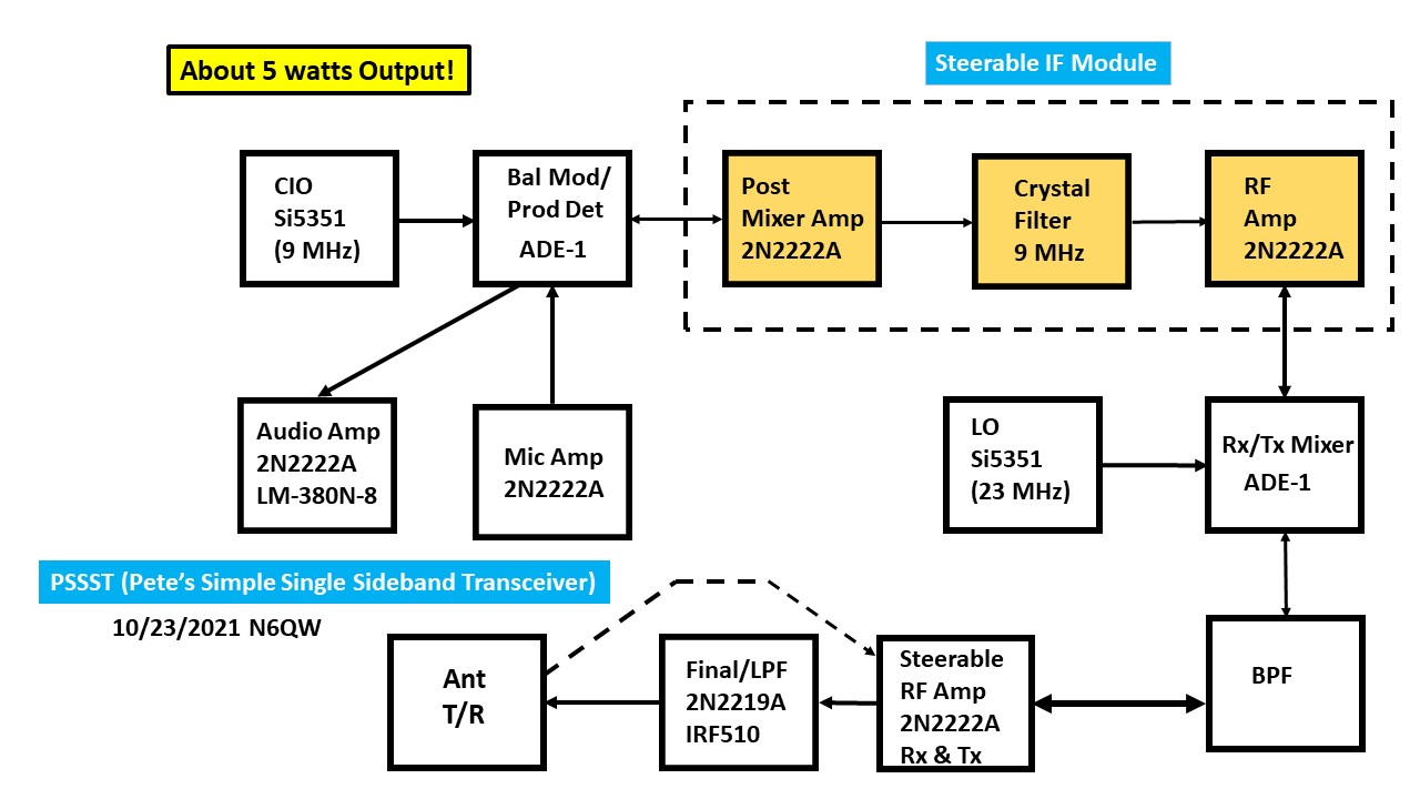
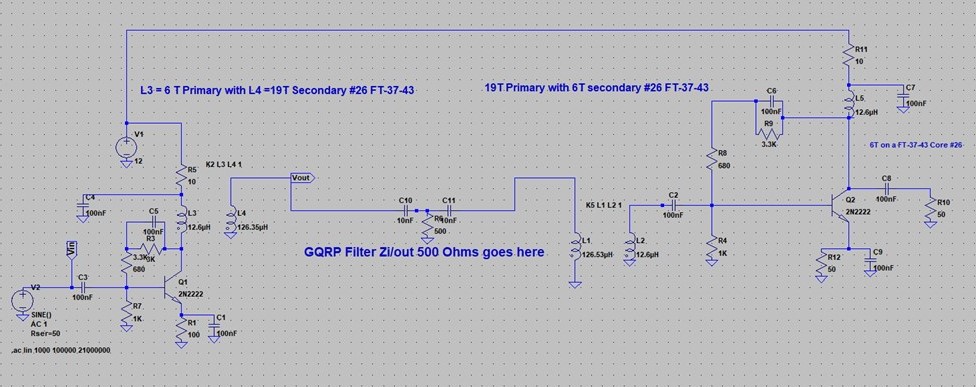
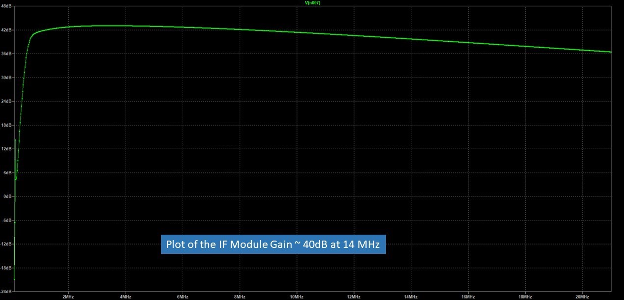
Steerable IF Module If there was ever a case of identifying who is doing all of the lifting --this is the Module! The idea for this came from another project of mine called "The Paesano" which was a take off from a transceiver built by the EA QRP Club called the The Perigrino (Pilgrim). In the EA deisgn the filter was switched between transmit and recieve. I extended that concept to switching the whole IF section not just the Filter. So the task was two fold with the first being coming up with suitable amplifier stage ahead of and following the Crystal Filter itself and the second piece was the steering of the module. The steering was the easy part as I have done that numerous times before. So in looking at the two amp stages and because the IF module is essentially steered between two double balanced mixers, the 1st stage is in effect a Post Mixer Amplifier (PMA). The second stage is nothing more than a RF Amplifier at the IF frequency. So if you dare read EMRFD or follow QEX or Solid State Design For the Radio Amateur, you know there is much said about the PMA. It has to be a strong amp for good IMD performance but also provide a constant impedance so no distortion to the Filter. The added task is that you don't "overrun the Filter with too much signal. In keeping with my Minimalist approach I ignored all of that mumbo jumbo; but just took a reasoned approach. Here is where I started. Firstly there are not a lot of amplifier stages in the rig. The second piece of that since it is steerable, there has to be sufficient gain for both transmitting and receiving. Thus read compromise and balance. Of equal importance is matching from the 50 Ohms of the DBM's to the IF Module and internally from the Amplifiers stages to the Crystal Filter itself. My GQRP Club Filter has a Zin/out of 500 Ohms. For other filters such as Spectrum Comms.UK they are either configured for 50 Ohms or 800 Ohms. From the manufacturer the actual impedance is 200 Ohms and there is a 4:1 matching transformer, which depending on how it is wired can give you 4:1 Up or 4:1 Down. BTW that is another issue with homebrew filters ~ finding the impedance to match. A poor match results in a lot of pass band ripple. Those who use a Nano VNA --it may be lying to you. Next we wanted to use the 2N22222A because we already knew that the PMA would run hot. Most of the Hayward designs have a 2N3866 or 2N5109 for the PMA --those are more than a 2N3904. As you will recall the 2N2222A in the TO-18 case style can be fitted with a heat sink. Now we also had to look at the gain across the whole module which says the net gain = PMA (Gain), Filter (Loss) and RF Amp (Gain). This is where LT Spice comes in the picture and a "PLUG" Gain Loss of the Filter of somewhere from 6 to 10 dB is not unrealistic. I did not use my two Nano VNA's (untrustworthy) to do any measurements and the plug number is in the typical range. A Loss of only 2dB in a filter is either spectacular or a faulty measurement. The Botton Line = likely across the Module we should see something greater than 30 dB and to have that consistent in both Receive and Transmit. SPECIAL NOTE: In the simulation you will see C10 and C11 with a 500 Ohm resistor stuck in between them. This is to simulate the crystal filter. These are NOT installed in the actual circuit. Simply connect the Filter to the Output side of the coil on the PMA and the Input side of the RF Amplifier stage. Given past experience this is good for two or three emails from those who don't read the information and simply connect things. In the last photo link you will see the Main Board where in the upper left corner, the Microphone Amp and in the upper right corner the Band Pass Filter. Also note the steering relays and the ADE-1 Double Balanced Mixers. Interspersed between the Mic Amp/Audio Amp Relay and the ADE-1 is an Audio Low Pass Filter comprised of a 1 MHy Choke and two 100nF caps. One of the Mixing products in the Product Detector is NOT Audio! There is one relay near the top of the Main Board next to the BPF. That relay on receive povides power to the Audio Amp. However on Transmit it powers the RF stages (Bias only to the IRF510/RD006HHF1) , the Microphone Amp, the Driver and power to the Linear Amplifier Switch. All other circuits are powered ON at all times. The wiring to the ADE-1's and the Three Relays is shown in the Main Link Wire Integration
|
|---|